Click here for details of the smelting experiments
In July 1969, the late Prof Henry Cleere conducted four experimental bloomery smelts at the Old Manor at Horam in East Sussex, the last two, on 26 and 27 July, being demonstrated to the public for the princely sum of one shilling (5p post decimalisation!). The wider event, ‘Horam Week’, was organised jointly by the Wealden Iron Research Group (WIRG) and the Sussex Industrial Archaeology Study Group.
WIRG recently came into possession of Henry’s records of these smelts which have been passed to the Historical Metallurgy Society for archiving. At that time, Henry was General Assistant Secretary of the Iron & Steel Institute which enabled him to coax funds, equipment and analytical facilities from the then British Steel Corporation (BSC), British Iron & Steel Research Association, (BISRA) and advice from various Universities. HMS also contributed with advice and some analysis via members. Indeed, as evidenced by the many letters Henry wrote to gain support, he even persuaded Monty Finniston – later to become Chairman of BSC – to authorise assistance. Items included the loan of an expensive Pt/PtRh thermocouple enabling temperatures in excess of 1000°C to be recorded, an Orsat gas analyser to calculate CO/CO2 ratios and an electric blower. Laboratory facilities provided analysis and metallographic examination of the products, including by transmission electron microscopy – a far more challenging technique than today’s more common scanning electron microscopy.
Henry’s bloomery furnace was based on his excavation of furnaces at Holbeanwood, an outlier of a Roman settlement at Bardown, near Ticehurst in East Sussex, dating from the first half of the second century. He used local clay following tests by BSC which showed it was sufficiently refractory and they recommended adding 20% pre-fired clay grog to reduce shrinkage, something Henry did not do as there was no archaeological evidence for this. Ore was collected from a local brick quarry at Sharpthorne. Wealden ores are largely iron carbonate – Siderite – typically containing 40% or so iron and are readily reducible after roasting.
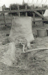
The furnace (Fig 1) had a slightly tapering internal shaft of hearth diameter 30cm and top diameter 20cm built around a central former from ‘sausages’ of puddled clay. The wall thickness was 9-12″ (23-30cm) and height initially 2′ 6″ (75cm) but extended to 3′ (91cm) after the first smelt. The interior and exterior walls were finished with a clay slurry and left to dry for six days followed by gentle firing with green wood.
The tuyere was inserted through the clayed-up slagging arch, each smelt using a different height or inclination. An alumina tube 19mm diameter was used for one trial as well as trumpet ended clay tuyeres and double tuyeres moulded within a single block of clay, based on rare finds at Bardown. Here, flagon necks had also been found, thought to have served as tuyeres, possibly for a roasting trench. The maximum height above the furnace floor was 6″ (15cm), dictated by the height of the slagging arch. A trench lined with clay was dug in front of the furnace to collect slag. Ore was roasted in pits, one square with a base of puddled clay, the other a trench 8′ x 1′ x 1′, (243 x 30 x 30cm) also puddled with clay, and open at one end, based on evidence from the Bardown excavation. Layers of charcoal and ore broken to 2-3″ (5-7.6cm) were spread in this and ignited. To accelerate roasting, air was blown in via a tuyere. Roasting was stopped when the ore turned red but subsequent analysis indicated that only the surface had been calcined – at least in the samples examined. The magnetic response of this ore erroneously led Henry to the conclusion that magnetite (Fe3O4) had resulted; subsequent XRD analysis of current smelts by WIRG have shown the product to be the magnetic form of Fe2O3, maghemite. The roasted ore broke easily and was screened to select material of 3/8 – 1″ (0.94-2.5cm), and charcoal of a similar size was screened for the smelt.
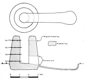
Four thermocouples were inserted through the back wall of the furnace at vertical intervals of 9″ (23cm) the lowest (T1) being 2″ (5cm) above the furnace base and the top one (T4) 5.5″ (14cm) below the rim of the furnace. Each was inserted 2” (5cm) into the charge. The lowest thermocouple was Pt/PtRh in order to measure temperatures in excess of 1000°C and the remainder chromel/alumel (Fig 2).
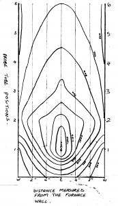
An isothermal plot on a diameter of the furnace normal to the tuyere axis showed a symmetrical heat pattern ranging from 1300°C closest to the tuyere to 600°C near the top of the furnace and 500°C at the hearth circumference (Fig 3).
The results of gas analysis taken every 30 minutes on smelt 2 – the longest and most successful – and smelt 3, showed that the level of CO2 rises and reaches a fairly steady value after ore charging has stopped. Completion of reduction was marked by a drop in CO2. A sudden drop in CO2 during charging indicates that reduction has stopped and something is wrong. A rough guide to the progress of the smelt is indicated by the flame at the top of the furnace. This burns strongly before reduction commences and dies down as reduction proceeds, sometimes to the extent of being extinguished.
Of the four smelts conducted, the second, which took place over the longest period of 10.5 hours, was the most successful producing a bloom weighing 19.5 lb (8.8kg) from 201 lb (91kg) of ore and 217.5 lb (98.6 kg) of charcoal, excluding that used to preheat the furnace. The charcoal to ore ratio was initially 1.5:1 for the first 2.5 hours resulting in an initial CO2/CO+CO2 ratio of 22, which then fluctuated between 14.3 and 20.3, dropping steeply to a steady 12 when the charcoal rate was reduced to 1:1. This level was maintained to the end of ore charging over the next 8 hours. The slag totalled 139 lb (63kg). A single tuyere was used for this smelt located 6″ (15cm) above the furnace base and elevated upwards 15°. The blower used provided a fixed air flow of 450l/min somewhat above the 300l/min recommended in the literature for this size furnace. Consequently, blowing was reduced by an unmeasured amount by moving the air hose away from direct contact with the tuyere. In an attempt to simulate the action of bellows, an intermittent blow was introduced after an hour and 10 min by blocking the air blow for two seconds in every five. This was carried out for an hour and resulted in a fall in temperature of 50-60°C for the lower three thermocouples and just 15°C for the top thermocouple. An acceleration in the downwards passage of the charge was noted due to the fluctuating pressure.
The other smelts produced little or no bloom, attributed in smelts 1 and 4 to heat lost during slag tapping by opening the arch too much and thereby reoxidising the bloom. In the case of smelt 3 the poor result was attributed to the inability to tap slag as a sandstone block had been used to seal the arch which welded into place and could not be removed. For smelt 4 a block of turf proved the most appropriate method of blocking the base of the slagging arch, this burning through when slag accumulated behind it producing a continuous run of slag from an aperture 6×2″ (15 x 5cm) for the remainder of the smelt. No attempt was made to empty the furnace on the same day of a smelt. Following a final charge of 2lb of charcoal, the furnace was left to burn down over night drawing natural draft through the tuyere and part-opened slagging arch. A steel lid was placed on top of the furnace.
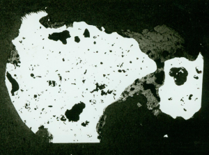
Sectioning of blooms (Fig 4) and metallographic examination of these and material forged to an arrow head as well as slag analysis were conducted. The bloom from trial 2 showed multiple voids and slag entrapment. Analysis revealed the iron to be almost completely ferrite of hardness 152HV5 this suggesting an appreciable quantity of phosphorus present.
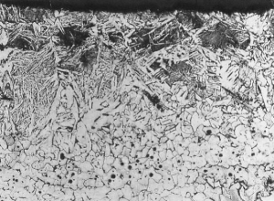
The shaft of the forged arrow head showed a carbon gradient from 0.1-0.2% at the centre to 0.7% at the surface, attributed to carburisation during forging (Fig 5).
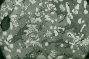
Slags were chemically and metallographically analysed by BSC. Furnace slag (Fig 6) was coarse crystalline enclosing charcoal fragments and contained pores encrusted with hercynite (FeOAl2O3) and fayalite (2FeO.SiO2). Some wustite (FeO), and iron monticellite (CaO.FeO.SiO2), were also present.
The fayalite crystals were up to 3mm long. The presence of a higher quantity of hercynite was considered unusual and a result of a high proportion of alumina in the ore (5-7% in three of four samples).
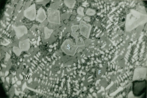
The tap slag (Fig 7) consisted of components of fayalite, hercynite, wustite, magnetite and iron monticellite with some locally occurring metallic iron, oxidised haematite and lime-rich pockets with dicalcium silicate and various calcium ferrite compounds (eg 2CaO.Fe2O3) or with anorthite crystals in a glassy matrix.
Today, WIRG continues the work of experimental smelting using a larger furnace of 60cm hearth diameter based on one excavated at Little Furnace Wood,near Mayfield. The lower third is constructed as a dome with a shaft of nominally 30cm internal diameter rising to a height of about 150cm.
Tim Smith February 2020